Applications/MTBCellCounter
MTB Cell Counter


The MTB_CellCounter plugin is available since release version 1.5 of MiToBo.
The plugin is based upon the original Cell Counter plugin for ImageJ written by Kurt De Vos (Cell Counter) and now available in Fiji. Compared to the original version the MTBCellCounter plugin adds some nice new features:
- pre-segmentation and filtering of spot-like structures
- free configuration of marker colors
- advanced editing of markers
- status bar, tooltips and keyboard shortcuts
Related Publications
- The Authors,"The 'MTB Cell Counter' - a versatile tool for semiautomated quantification of sub-cellular phenotypes in fluo-
rescence microscopy images".
2015, submitted for publication.
Name of Plugin/Operator
mtb_cellcounter.MTB_CellCounter
(available since MiToBo version 1.5)
Usage
For using the plugin you need to install MiToBo by following the instructions on the Installation page. Running ImageJ you will then find a new entry 'MiToBo' in the plugins menu from where you can select the 'MTB CellCounter' plugin.
The usage of the plugin is leaned on the usage of the original plugin (see also Cell Counter webpage).
The basic workflow is as follows:
- open the image you would like to process and press the 'Initialize' button
- optionally configure the particle detector via the 'Configure operator...' button and then press 'Detect'
- once the detection is finished you can filter detected particles via the 'Filter Particles...' button by size and average intensity; if you are done, press 'Select Markers'
- now markers can manually be postprocessed, i.e. markers can be added or removed, or their type can be changed
- at the end you can view marker statistics (button 'Results'), save the markers to a file (button 'Save Markers') or do some measurements (button 'Measurements...')
Functions and Options
Below we outline the functions of the various elements of the graphical user interface.
- Initialization:
- 'Initialize': initializes the plugin with the active image, if the image has more than one channel only the first channel is considered
- 'Keep original': if checked the source image remains open, otherwise it is closed
- Pre-segmentation:
- 'Detect': runs the particle detector
- 'Configure Operator...': allows to change the parameters of the particle detector
- 'Filter Particles...': allows to filter detection results
- 'Show contours': enables/disables display of the contours of detected particle regions
- 'Select markers': selects the final set of markers and terminates detection stage
Detected particles are labeled with marker type 1 and the counter of that type refers to their number.
- Manual post-processing:
- 'Add': add a new marker type at the end of the list, the type gets a random color
- 'Remove': delete the last type from the end of the list
- 'Delete': delete the last placed marker
- Parameters:
| Name | Description |
| Image directory | directory where the input image data can be found |
| Mask directory | directory where the label images or region boundary files can be found |
| Mask format | format of the segmentation data files: LABEL_IMAGE = images with unique labels for each cell and a value of zero for the background / IJ_ROIS = set of ImageJ 1.x ROIs, one ROI for each cell |
| Output and working directory | directory to which the result files and intermediate data is written |
| Calculate features | if disabled the operator expects the features to be already present in the input directory and skips the (time-consuming) feature calculations; this option is helpful if the features have already been calculated ones and only the parameters of the clustering should be changed |
| Feature directory | directory where the features should be saved or - in case they are already available - from where they are read; the directory can be the same as the output and working directory |
| Tile size x/y | size of the sliding window used for feature calculations, should be chosen according to the resolution of the input images |
| Tile shift x/y | shift of the sliding window, if the shift is smaller than the tile size sliding windows overlap |
| Distance | pixel-pair distance in co-occurence matrix calculations |
| Set of directions | directions to be considered in co-occurence matrix calculations |
| Isotropic calculations | the texture features are derived from co-occurence matrixes; if this flag is enabled features for different directions are averaged, otherwise all individual directions are preserved (resulting in larger, but also more informative feature vectors) |
| Number of feature clusters | number of clusters in first stage, i.e., number of expected structural patterns in the images |
| Do PCA in stage II? | allows to enable/disable PCA on the cluster distribution vectors prior to the pairwise distance calculations; by default enabled |
Additional Tools
The hierarchical clustering in stage II of our approach as described in the paper has been done using the MultiDendrograms software.
In principal every hierarchical clustering tool can be applied.
The basis for the hierarchical cluster analysis is the file AllImagesPairwiseDistanceData.txt to be found in the output directory upon termination of an analysis run. It contains a matrix of pairwise Euclidean distances of the (optionally dimension-reduced) cluster distribution vectors of all cells. The file can directly be loaded by MultiDendrograms, for other tools format convertion might be necessary.
You can download the latest version of MultiDendrograms from its webpage: [1]
Sample data
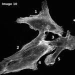
For testing the ActinAnalyzer2D operator we provide some sample data: ActinAnalyzer2D sample data
The archive contains the following sub-folders:
- imageData: test images that were used in the ICPR publication mentioned above
- maskData: corresponding label images
- featureData: pre-calculated features for the cells (re-calculating the features may require up to an hour, depending on the machine used)
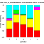
- resultData: sample results calculated on the given data
In addition, in the archive a file with a sample parameter configuration for the operator can be found. The parameters are those used for producing the sample results. Once the operator has been started the file can be loaded via the 'File' menu and its entry 'Load Settings' . Note that you need to set the image and mask directories, and also the feature directory according to your local file system structure and the place to where you extracted the zip file.
For more information on the data and the morphological analysis of the cells, see
Anne Zirkel, Marcell Lederer, Nadine Stöhr, Nikolaos Pazaitis, and Stefan Hüttelmaier
IGF2BP1 promotes mesenchymal cell properties and migration of tumor-derived cells by enhancing the expression of LEF1 and SNAI2 (SLUG)
Nucleic Acids Res. Jul 2013; 41(13): 6618–6636. Published online May 15, 2013. doi: 10.1093/nar/gkt410, Article
Updates
July 2014
- Released first version of Actin Analyzer as published in ICPR 2014.